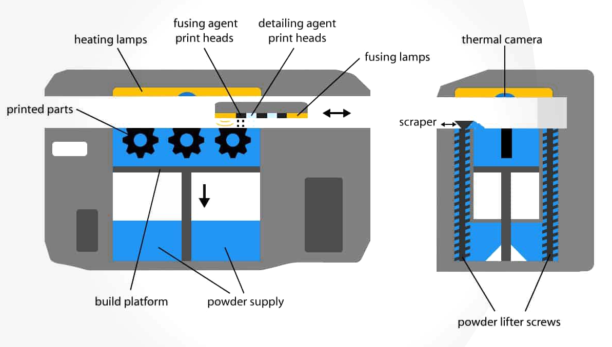
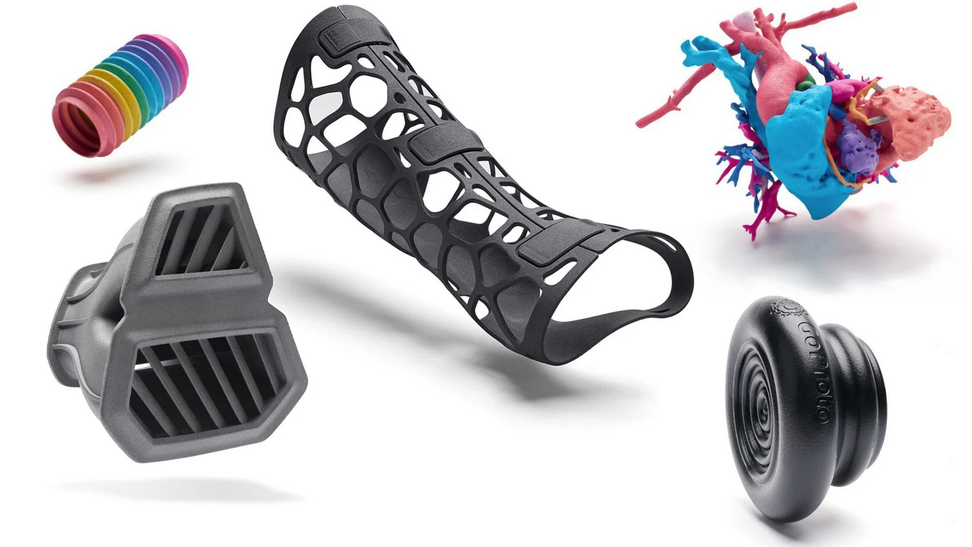
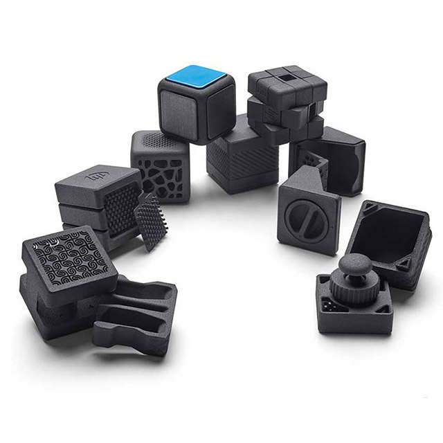
Multi Jet Fusion (MJF) is HP’s proprietary 3D printing process. In MJF, parts are built by jetting a binding agent onto thin layers of polymer powder particles (typically nylon) and then sintering them using an IR heat source. MJF produces functional plastic parts with isotropic mechanical properties that can be used for detailed prototyping or end-use low-volume production.
In MJF, parts are built by jetting a binding agent onto thin layers of polymer powder particles (typically nylon) and then sintering them using an IR heat source. With a layer height of 80 microns, parts have high density and low porosity, compared to PA 12 parts produced with Laser Sintering.
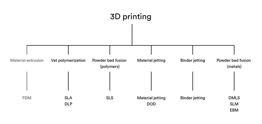
Although new products continually emerge within additive manufacturing, outpacing the power of the original 3D printing systems developed in the mid-80s is still a challenging feat. Enter the mighty technology known as Multi Jet Fusion (MJF) though–built on the benefits and premises of previous conventional and 3D printing technologies.
Upload your 3D Printing supported files, receive an instant HP Multi Jet Fusion 3D printing quote and get your parts into production in less than 5 minutes.
From prototyping to small-batch production, our global network of certified MJF 3D printing facilities will allow you to produce highly accurate parts with quality comparable to injection molding.
| Capabilities | Description |
|---|---|
| Maximum build size * | 380 x 285 x 380 mm (14.9'' x 11.2'' x 14.9'') |
| Standard lead time * | 3-5 business days |
| Dimensional accuracy | ± 0.3% with a lower limit on ± 0.3 mm (0.012'') |
| Layer thickness | 80 μm |
Note: For expedited shipping or parts that exceed the maximum build size contact sales@ug3ds.com
The table below summarizes the recommended and technically feasible values for the most common features encountered in 3D printed parts.
| Feature | Recommended size |
|---|---|
| Unsupported walls | 1.0 mm (0.040'') |
| Supported walls | 0.7 mm (0.030'') |
| Minimum detail size | 0.25 mm (0.010'') |
| Minimum hole size | 1.0 mm (0.040'') |
| Moving parts | 0.5 mm (0.020'') between moving surfaces |
| Assembly clearance | 0.4 mm (0.016'') between mating surfaces |
| Maximum wall thickness | 20 mm (0.8''). Thicker parts must be hollowed and contain at least two escape holes for powder removal with a min. diameter of 8 mm (0.3''). |
Learn more about the process in our Knowledge Base article.
| Lifecycle | Lead Time | Materials | Resolution |
|---|---|---|---|
| Functional testing, low to mid volume prototyping (10s - 100s) | 3-5 days | PA12 MJF | 80 μm |

I appreciate Unified Global 3D Solutions effort to understand our requirement and our end application and assist us in identifying the correct prototyping technology rather than just printing our designs.
M Venkatesh
Apollo Laboratories (P) Ltd.

We are happy in Unified Global 3D Solutions product development capability - the design thinking and manufacturability centric approach aided us in cost reduction and getting the aesthetics spot on.
Sivamallikarjuna Reddy
Aodh Lifesciences
Unified Global 3D Solutions is prompt in work and clear in communication. The professional design of enclosure was done perfectly to the required specs. I strongly recommend him for others seeking Product design / 3d printing services.
Vishwanath
Scatter 2x2