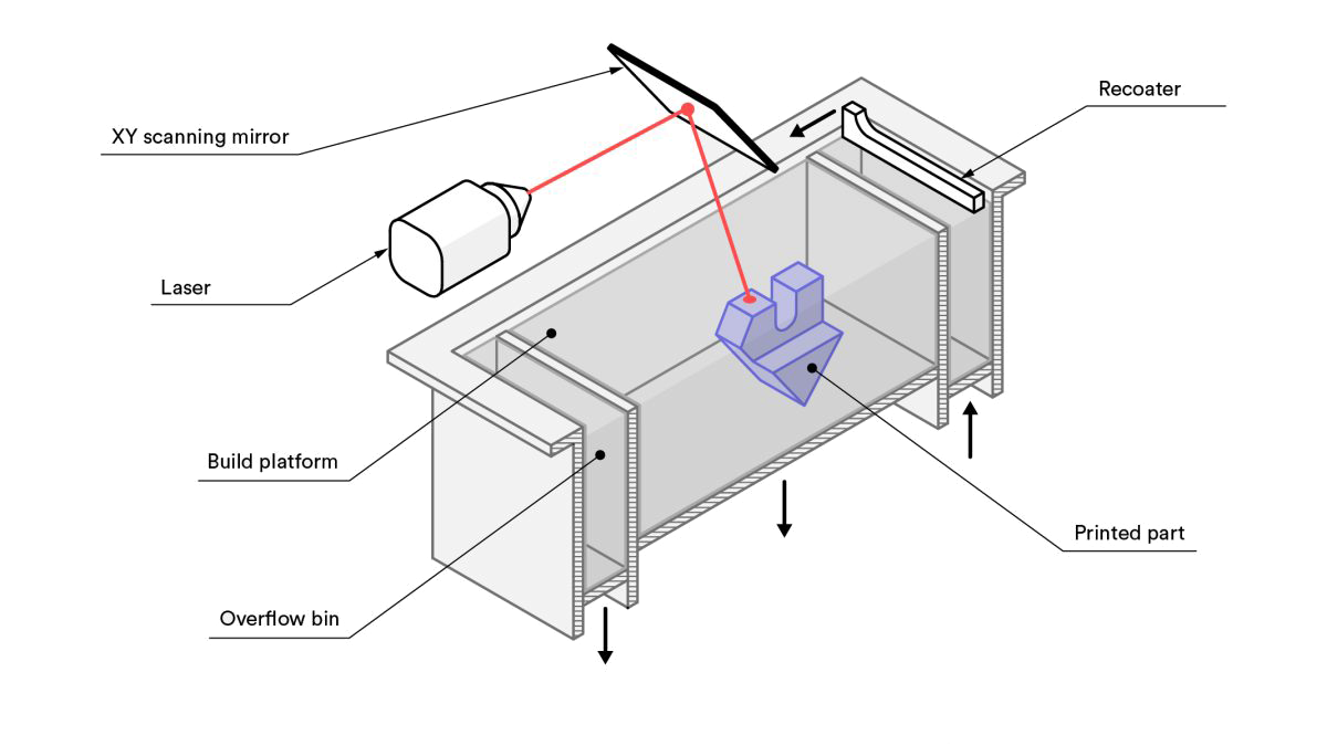
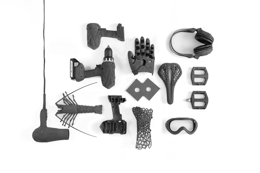
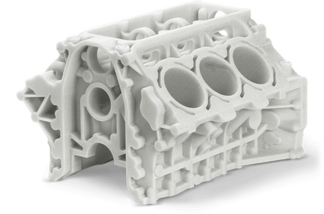
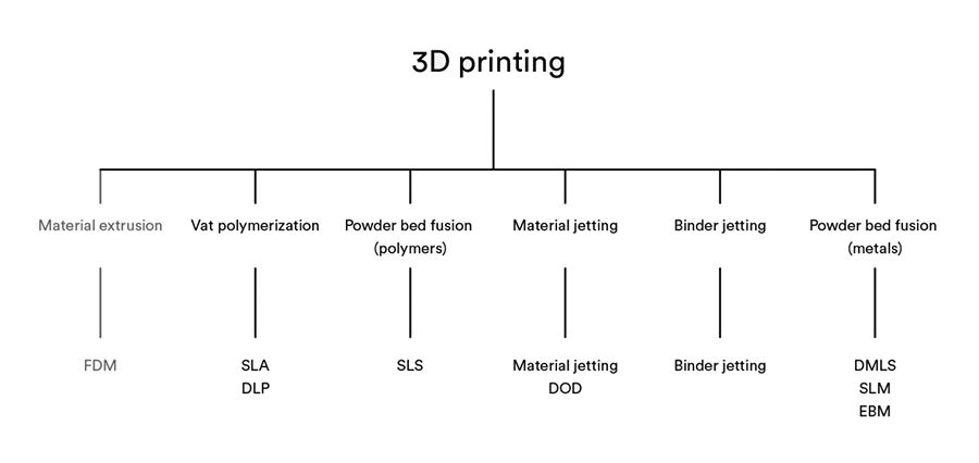
Selective Laser Sintering (SLS) is an industrial 3D printing process ideal for manufacturing end-use parts. In SLS, a laser selectively sinters polymer powder particles, fusing them together and building a part layer-by-layer. SLS produces functional plastic parts with isotropic mechanical properties that can be used for detailed prototyping or end-use low-volume production.
Selective Laser Sintering uses high-powered lasers to sinter powdered material, binding it together to create a solid structure. It is often confused with another similar process called Selective Laser Melting (SLM), the difference being that it only sinters the powders together as opposed to achieving a full melt.
Parts are supported by unsintered powder in each layer, which remain spread across the build volume until each layer is fused together. Once complete, the part is removed from the remaining powder and cleaned by hand and using water/air jets.
Upload your 3D Supported files, receive an instant Selective Laser Sintering 3D printing quote and get your parts into production in less than 5 minutes.
From prototyping to small-batch production, our global network of certified SLS 3D printing facilities will allow you to produce highly accurate parts with quality and strength comparable to injection molding.
| Standard capabilities | Description |
|---|---|
| Maximum build size * | 15.53" x 19.68" x 15.53" (395 mm x 500 mm x 395 mm) |
| Lead time * | 3-5 business days |
| Dimensional accuracy | ± 0.3% with a lower limit of ± 0.3 mm (± 0.012”) |
| Layer thickness | 100 μm |
Note: For expedited lead times or parts that exceed the maximum build size contact sales@ug3ds.com
The table below summarizes the recommended and technically feasible values for the most common features encountered in 3D printed parts.
| Feature | Recommended size |
|---|---|
| Unsupported walls | 1.0 mm (0.040'') |
| Supported walls | 0.8 mm (0.031'') |
| Minimum detail size | 0.8 mm (0.031'') |
| Minimum hole size | 1.0 mm (0.040'') |
| Moving parts | 0.5 mm (0.020'') between moving surfaces |
| Assembly clearance | 0.4 mm (0.016'') between mating surfaces |
| Maximum wall thickness | 20 mm (0.8''). Thicker parts must be hollowed with and at least two escape holes for powder removal with a min. diameter of 8 mm (0.3''). |
| Lifecycle | Lead Time | Materials | Resolution |
|---|---|---|---|
| Functional testing, low to mid volume prototyping (10s - 100s) | 3-5 days | PA12, PA12 GF 50% , PA6 GF 20% | 100 μm |
I appreciate Unified Global 3D Solutions effort to understand our requirement and our end application and assist us in identifying the correct prototyping technology rather than just printing our designs.
M Venkatesh
Apollo Laboratories (P) Ltd.
We are happy in Unified Global 3D Solutions product development capability - the design thinking and manufacturability centric approach aided us in cost reduction and getting the aesthetics spot on.
Sivamallikarjuna Reddy
Aodh Lifesciences
Unified Global 3D Solutions is prompt in work and clear in communication. The professional design of enclosure was done perfectly to the required specs. I strongly recommend him for others seeking Product design / 3d printing services.
Vishwanath
Scatter 2x2